
Diagram of Signals and Direction Chart [New Lynn]
Maker and role
New Zealand Rail, Attributed to
See full details
Object detail
Accession number
2011.294
Maker
Description
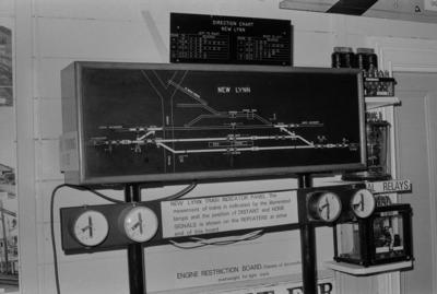
A wood box filled with electrical wiring that light up the external face which features a diagram of the lines at New Lynn Station. There is a separate chart affixed to the top containing more data relating to the station.
Brief History
This Diagram of Signals was part of the signalling equipment in the signal box at Auckland’s New Lynn station, located on the North Auckland Line. The signal box was installed in 1915 and operated until the late 1960s during the time when New Zealand Railways used semaphore or mechanical signalling. From about 1939 the diagram of signals were made using oil colours on a black steel plate, like this object. They replaced the earlier red and black ink with water colours on card.
The electric current (or track circuit) passed from rail to rail by a passing train would activate a light on the panel to indicate the train’s location on the diagram of signals. The diagram identifies a lever in the signal box by number and the function of each lever is further identified by colour of the lever and face plate. For example, a green lever indicates distant signals (e.g. number 1 and 24 on the diagram). It is these signals that control the movement of trains and instructs the driver to stop (signal at stop, or red) or proceed (green) to the next section or block. The diagram of signals also identifies individual track sections. The break in the green lines indicate the position of an insulated joint, which allows for the isolation of the next section.
The Direction Chart above the diagram of signals shows the sequence the levers are to be reversed (or pulled) to set up a particular route. For example, if a passenger train is approaching from the Auckland end (Track Section ‘B1’) and needs to stop on the Down Main (‘B3’) at the platform, then proceed north (‘A3’), the Direction Chart indicates the order in which the levers are to be reversed to allow that movement. For example, from ‘B1’ to ‘A3’ the following levers require to be reversed; 6, 9, 16, 18, 19, 3, 2, 1 (3,2 and 1 are signals). Note the points at 7, 10, and 17 stay as set in the normal position and don’t require reversing. Points and signals are always set in the normal position unless required for an alternative movement.
The back of this object was rewired by MOTAT in the 1970s, with help of telephone exchange parts, to activate the lights on the panel to indicate the movement of a train passing through the 'New Lynn' yard. When displayed by MOTAT the diagram box was also mounted on top of a bank of semaphore electrical signal indicators which are linked to this record as a related object.
Marks
New Lynn
DIRECTION CHART / NEW LYNN Printed
DIRECTION CHART / NEW LYNN Printed
Media/Materials
Other name
Indicator Panel
Credit Line
New Zealand Rail. Diagram of Signals and Direction Chart [New Lynn], 2011.294. The Museum of Transport and Technology (MOTAT).
![Electrical Signal Indicators [Semaphore]](https://collection.motat.nz/records/images/medium/35357/f86eef8fe6ca624a1a4e9b4820f86118accbeaa7.jpg)
Public comments
Be the first to comment on this object record.